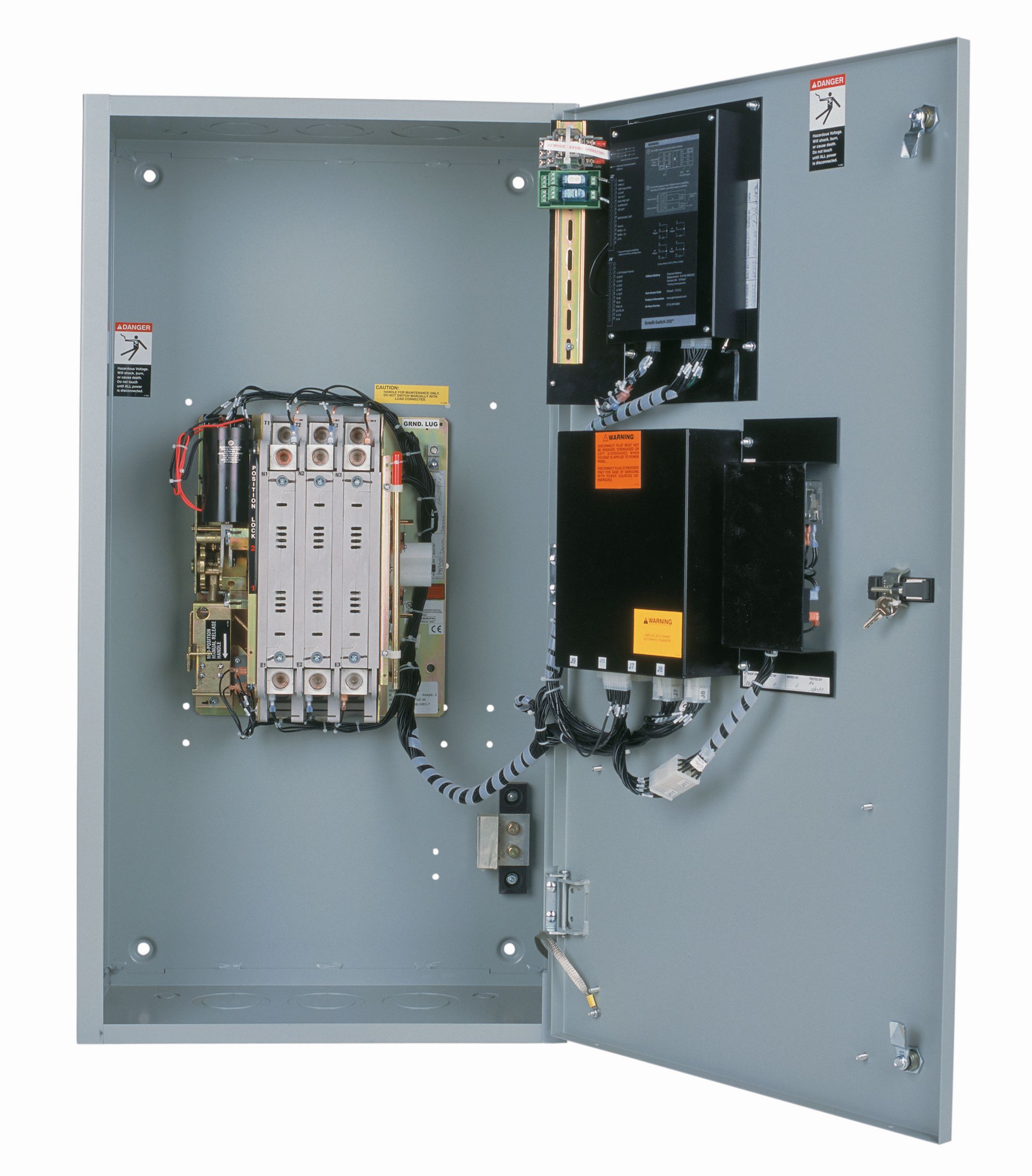
The Cat® CTS Series Automatic Transfer Switch(ATS)is configurable for applications requiring the dependability and ease of operation found in a full featured power contactor type transfer switch.
The CTS Series is equipped with the MX250 controller that is designed for the most demanding transfer or bypass switch applications.
Technical Summary
- Rating Range
- 40 to 4000A
- Transfer Type
- Open transition
- Switch Type
- Contactor Based
Electrical Ratings
- Control Power
- 40 to 4000 amperes, 2, 3 or 4 Poles
- Enclosure Capability
- NEMA 1, 3R, 4, 4X and 12
- System Voltage Application
- Available to 600 VAC, 50 or 60 Hz
- Applicable Testing
-
UL 1008 listed at 480 VAC
CSA C22.2 No. 178 certified at 600 VAC
IEC 947-6-1 listed through 480 VAC
Standard Equipment:
- The Cat Cts Series Of Automatic Transfer Switches
- The Cat CTS Series power contactor type transfer switch makes use of a fully programmable / configurable microprocessor-based controller to allow the utmost in application flexibility. Further, the CTS Series is offered in a wide array of configurations enabling it to meet the needs of even the most highly critical load.Available configurations include:
- 40-4000 Amps:
- CTSD Delayed Transition Transfer Switches
- CTSM Manual Transfer Switches
- CTS Automatic Transfer Switches
- 100-4000 Amps:
- CTSCT Closed Transition Transfer Switches
- CBTSD Delayed Transition Bypass Switches
- CBTSCT Closed Transition Bypass Switches
- CBTS Automatic Transfer/Bypass Switches
- All Cts Products Meet Or Exceed Industry Requirements To Allow Specification And Installation With Confidence.
- Codes and Standards: NFPA 0,99, 101,110,NEC 517,700,701,702,IEEE 446, 241,NEMA ICS2-447
- CSA C22.2 No. 178 listed through 600 VAC
- Quality System:
ISO 9001 Registered - UL 1008 listed through 480 VAC
- Controls tested in accordance with:
- Equipment (Controls and Power Section)Seismic Test Qualified to:
IBC-2003
IEEE-693-2005 - Enclosures meet the requirements of:
UL 508, UL 50, ICS 6, ANSI C33.76 and NEMA 250 - IEC 947-6-1 listed through 480 VAC
- This ruggedly built family of power contactor switches has been specifically designed for transfer switch duty with dependability, versatility and user friendliness of prime concern.
The CTS power panel components, consisting of power switching contacts, drive mechanism and terminal lugs, are mounted on a specially formed backplane. Logic devices including microprocessor control auxiliary time delays and special accessory equipment are assembled on the door for ease of maintenance and separation from the power section. They are connected with a numbered wiring harness equipped with a disconnect plug that allows isolation of the control panel for maintenance.
- Cts Series Method Of Operation
- When the normal source fails or the voltage drops to a predetermined point (usually 80% of nominal), if required, a circuit is closed to start the engine generator set. When the emergency source reaches 90% of rated voltage and 95% of rated frequency, the drive solenoid is energized through the emergency coil control relay, causing the main contacts to disconnect the load from the normal source and connect it to the emergency source. After the drive solenoid has completed its electrical stroke and is seated, the emergency coil control relay opens to disconnect it. The transfer switch is now mechanically locked in the emergency position. When normal voltage is the normal source and connect it to the emergency source. After the drive solenoid has completed its electrical stroke and is seated, the emergency coil control relay opens to disconnect it. The transfer switch is now mechanically locked in the emergency position. When normal voltage is and is seated, the coil control relay opens to disconnect it. The transfer switch is now mechanically locked in the normal position.
- Drive Mechanism
- All CTS switches employ the simple “over-center” principle to achieve a mechanically locked position in either normal or emergency and a high speed drive assures contact transfer in 100 ms or less. High contact pressure and positive mechanical lock allow for high withstand and closing ratings, far exceeding UL requirements.
Optional Equipment:
Specifications
Technical Summary
- Rating Range
- 40 to 4000A
- Transfer Type
- Open transition
- Switch Type
- Contactor Based
Electrical Ratings
- Control Power
- 40 to 4000 amperes, 2, 3 or 4 Poles
- Enclosure Capability
- NEMA 1, 3R, 4, 4X and 12
- System Voltage Application
- Available to 600 VAC, 50 or 60 Hz
- Applicable Testing
-
UL 1008 listed at 480 VAC
CSA C22.2 No. 178 certified at 600 VAC
IEC 947-6-1 listed through 480 VAC
Standard/Optional Features
Standard Equipment:
- The Cat Cts Series Of Automatic Transfer Switches
- The Cat CTS Series power contactor type transfer switch makes use of a fully programmable / configurable microprocessor-based controller to allow the utmost in application flexibility. Further, the CTS Series is offered in a wide array of configurations enabling it to meet the needs of even the most highly critical load.Available configurations include:
- 40-4000 Amps:
- CTSD Delayed Transition Transfer Switches
- CTSM Manual Transfer Switches
- CTS Automatic Transfer Switches
- 100-4000 Amps:
- CTSCT Closed Transition Transfer Switches
- CBTSD Delayed Transition Bypass Switches
- CBTSCT Closed Transition Bypass Switches
- CBTS Automatic Transfer/Bypass Switches
- All Cts Products Meet Or Exceed Industry Requirements To Allow Specification And Installation With Confidence.
- Codes and Standards: NFPA 0,99, 101,110,NEC 517,700,701,702,IEEE 446, 241,NEMA ICS2-447
- CSA C22.2 No. 178 listed through 600 VAC
- Quality System:
ISO 9001 Registered - UL 1008 listed through 480 VAC
- Controls tested in accordance with:
- Equipment (Controls and Power Section)Seismic Test Qualified to:
IBC-2003
IEEE-693-2005 - Enclosures meet the requirements of:
UL 508, UL 50, ICS 6, ANSI C33.76 and NEMA 250 - IEC 947-6-1 listed through 480 VAC
- This ruggedly built family of power contactor switches has been specifically designed for transfer switch duty with dependability, versatility and user friendliness of prime concern.
The CTS power panel components, consisting of power switching contacts, drive mechanism and terminal lugs, are mounted on a specially formed backplane. Logic devices including microprocessor control auxiliary time delays and special accessory equipment are assembled on the door for ease of maintenance and separation from the power section. They are connected with a numbered wiring harness equipped with a disconnect plug that allows isolation of the control panel for maintenance.
- Cts Series Method Of Operation
- When the normal source fails or the voltage drops to a predetermined point (usually 80% of nominal), if required, a circuit is closed to start the engine generator set. When the emergency source reaches 90% of rated voltage and 95% of rated frequency, the drive solenoid is energized through the emergency coil control relay, causing the main contacts to disconnect the load from the normal source and connect it to the emergency source. After the drive solenoid has completed its electrical stroke and is seated, the emergency coil control relay opens to disconnect it. The transfer switch is now mechanically locked in the emergency position. When normal voltage is the normal source and connect it to the emergency source. After the drive solenoid has completed its electrical stroke and is seated, the emergency coil control relay opens to disconnect it. The transfer switch is now mechanically locked in the emergency position. When normal voltage is and is seated, the coil control relay opens to disconnect it. The transfer switch is now mechanically locked in the normal position.
- Drive Mechanism
- All CTS switches employ the simple “over-center” principle to achieve a mechanically locked position in either normal or emergency and a high speed drive assures contact transfer in 100 ms or less. High contact pressure and positive mechanical lock allow for high withstand and closing ratings, far exceeding UL requirements.


